3D printing for product designers: form and fit prototypes before tooling
Updated · 8 min read
Give a product prototype one physical question to answer. Separate form, assembly fit and function, then carry a clear learning record into the next CAD revision and tooling discussion.
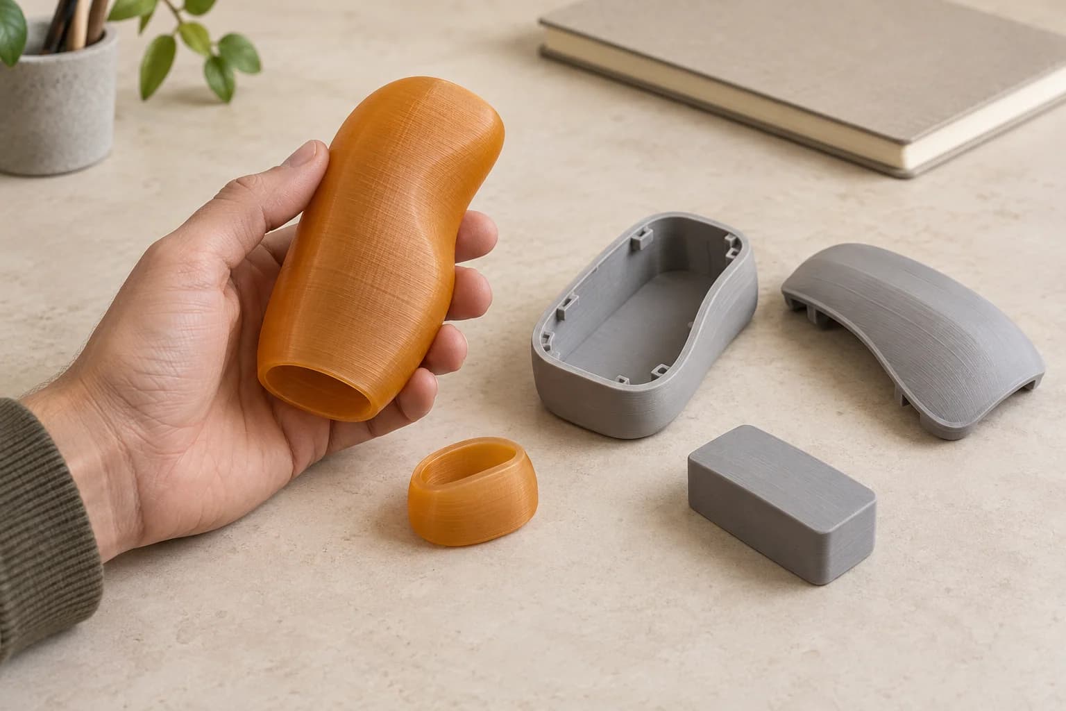
Before ordering a prototype, finish this sentence: “After holding or assembling this sample, we need to decide whether…” A clearer grip shape? A different opening? A removable end cap? That decision gives the print a job and gives the review a useful stopping point.
For product designers and startup teams in Toronto, we recommend a full-size form study or low-consequence assembly mockup when a screen view leaves a physical question unresolved. Record what it teaches before revising the CAD. Production readiness needs its own review.
Decide whether you need form, assembly fit or function
“We need a prototype” leaves too much unsaid. Use the following working distinction when briefing the designer and the people who will review it.
| Purpose | A concrete review question | What a promising sample still leaves open |
|---|---|---|
| Form | Can someone hold the full-size shape comfortably and reach the intended finger position? | Final weight, soft-grip feel, surface finish and durability |
| Assembly fit | Can the intended pieces enter, align and come out in the planned order? | Production dimensional variation, joint strength and retention over time |
| Function | Does the product perform its intended job under defined conditions? | A separate test plan using appropriate construction, materials and acceptance criteria |
A handle-shaped form model can help you discuss where the palm sits without being fitted to a tool or carrying torque. An end-cap mockup can show how the seam looks and where fingers would go. A nonpowered shell can be reviewed with solid, inert stand-ins for the components inside it.
Keep those samples within their stated purpose. We cover visual and fit prototypes here, not operating electrical housings, loaded mechanisms or safety-critical parts. If the next decision depends on heat, sealing, impact, electrical protection or structural performance, involve the relevant specialist and choose a representative prototype and test method.
What a physical sample changed in a documented project
Prusa's interview with Linus Media Group engineering manager Kyle Tharratt gives a specific example. Alex Clark made physical handle iterations for feedback. Tharratt then explored about 17 end caps while Linus held the prototype, followed by a resin model with the intended internal features before the tooling decision.1
The useful lesson is the sequence: make the outside discussable, resolve a detail, then change the sample for the next question. That team's results do not establish what our prints can do.
OXO's lab offers another distinction. In Formlabs' account, Jesse Emanuel describes requests for basic form models, functional models and presentation parts from different teams. The lab uses both resin and filament processes.2 These are vendor-published accounts of named practitioners, rather than independent comparisons. They support choosing a sample for its audience and purpose; their speeds, materials and performance do not describe our service.
Name the people whose decision matters. An outline review needs the whole volume; an assembly-access review needs the opening and neighbouring geometry. A presentation review may need a different finish.
Prepare the geometry around the question
Keep the editable CAD master and give the export a traceable revision. Decide which features matter: a blank interior may suffice for proportions, while an assembly-access review needs the obstructions, cover and mating piece.
In Autodesk Fusion, for example, Save As Mesh provides choices for format, units and whether bodies are saved together or separately.3 Make those choices deliberately, then check the physical size in the slicer. A mesh exported as .3mf can still be geometry awaiting slicing; the extension alone does not make it an order-ready toolpath.
We suggest five checks before slicing:
- Full-size geometry. If hand position is the question, review it at the intended size. Identify any intentionally scaled model clearly.
- Separate pieces. Keep a removable cover or end cap separate when the review needs to examine its position or removal sequence.
- Representative surroundings. Use the actual mating item where appropriate, or an inert stand-in whose revision and differences are recorded.
- Important surfaces. Identify where fingers touch, where pieces meet and where the reviewer will look at the seam.
- Print representation. Inspect the sliced layers, small features, support locations and access for removing supports.
Prusa's support guidance notes that reorienting or splitting a model can reduce support requirements, and that support contact can leave surface imperfections.4 That matters when the review question concerns the very face being supported. Record any sanding, trimming or other cleanup: a cap that fits after adjustment is a different observation from one that fits as received.
Choose from the stocked materials shown during ordering. Write down the selected material and orientation with the review record. Do not assume that a filament sample reproduces the intended soft-touch surface, final mass or moulded material behaviour.
Keep a prototype learning record beside the CAD
IDEO.org's prototyping method starts with what the team wants to learn, then calls for observation and a written debrief. Its feedback guidance encourages honest reactions, including negative ones, and recording what people say.56
Here is our adaptation for a form or assembly-fit review. Keep it and the photographs with the same project revision.
| Record | What to write |
|---|---|
| Identity | Project, part, CAD revision and sliced-file revision |
| Decision | The one decision this sample should inform |
| Representation | Included geometry, omitted features and inert substitutes |
| Print context | Material, orientation and any cleanup |
| Mating context | Actual mating item or stand-in, with its revision |
| Review | Date, reviewer and the handling or assembly task |
| Observation | What happened, before explaining why |
| Feedback | The reviewer's words, kept separate from your interpretation |
| Next change | The proposed CAD revision and why |
| Still unanswered | Questions requiring another sample, process or specialist review |
Consider this hypothetical example: a team is developing a small desk-product shell containing a removable solid insert. The sample has a body, a front cover and an inert block representing the insert. There is no powered equipment inside.
The question is whether the insert can be removed through the intended opening while the front cover stays attached. During the review, the block catches on an internal lip. The reviewer takes off the cover before withdrawing it.
The observation should say, “Insert could be withdrawn only after removing the front cover.” The interpretation might be, “Our proposed service sequence is obstructed.” The next change could be to revise the opening or to make cover removal part of the intended sequence. Those are different design decisions; “doesn't fit” would conceal the choice.
Also record what went well. The outside proportions may be easy to handle while removal needs work; preserve that distinction in the next revision.
Bring unresolved questions to the tooling discussion
Take the record, labelled sample, photographs and current CAD to the manufacturing conversation. State what was observed and omitted. “The insert passed this opening in revision C” is more useful than “the prototype is approved.”
Material extrusion builds an object layer by layer, as NIST describes.7 Injection moulding has its own geometry and process considerations: Protolabs' design guidance separately addresses draft, undercuts and wall thickness.8 Our practical inference is that a successful printed assembly does not settle whether the intended moulded geometry is manufacturable or how production variation will affect its fit. Those questions belong in the tooling supplier's review.
Sometimes an earlier or different representation is enough. We suggest a paper outline for a layout question or a cardboard or foam volume for rough proportions. IDEO.org's method allows models, mockups and other ways of making an idea tangible.5 If the decision instead needs a soft surface, a particular finish or representative production construction, ask a specialist prototype supplier which process can show it. We do not offer resin printing, machining or finishing through this print-order flow.
Order a prototype print in Toronto
We print authorized customer models supplied as compatible pre-sliced .3mf or .gcode files. An unsliced .3mf has an opt-in auto-slice path, subject to availability. We do not create CAD from an idea, photograph or screenshot, repair models or accept raw STL as a checkout file.
If you have geometry only, use our STL-to-print-ready guide, then follow the plate slicing and export steps. Our .gcode.3mf explanation helps distinguish a saved model from a sliced export.
Confirm that you own the design or have permission to reproduce it, including permission to send a client's model for fabrication. The named projects above are learning examples, not sources of downloadable designs. Check the service restrictions before ordering.
When the file is ready, upload it for a quote, check the parsed print details and select a compatible stocked filament. Our Toronto printing-cost guide explains what affects the CAD quote. Free scheduled Toronto pickup and Canada Post shipping follow the available ordering options. Plan the review after the sample arrives, with the mating items and learning record ready.
When the decision is visual proportion, the interior-mockup comparison method shows why a common context and a separate finish sample make feedback more useful.
When one prototype question needs several candidates, the handle, knob and shell comparison worksheet keeps a common reference and separates observations from explanations.
For a merchandising application, the small retail-display guide adds the product, counter footprint, replenishment access and stock-stand comparison to the prototype brief.
Questions product teams ask before the first print
Does a handle form model need the working mechanism?
Include it only if it is needed to answer the stated question, and use an inert representation for this kind of review. A shape study can omit a mechanism, but the record should say that final weight, balance and operating behaviour remain unanswered.
Can a shell that fits in filament go straight to injection moulding?
Treat the fit as an observation about that sample. Give the manufacturing supplier the intended production CAD and fit requirements for its own review. Moulding-specific draft, undercuts and wall thickness still need consideration.8
How much clearance should we add between the pieces?
We do not prescribe a universal clearance. Start with the designer's intended relationship, identify the surfaces being checked and document the received sample. If it binds or needs adjustment, record where before changing the CAD and reslicing. A hand-adjusted fit should be described as such.
Can we send an STL or a CAD screenshot and have you design the prototype?
A screenshot is not printable geometry, and CAD design is outside this service. With an authorized STL, prepare a compatible sliced file using the linked guide. With an unsliced .3mf, check whether the opt-in auto-slice route is available. If the geometry does not exist yet, work with a designer first.
Sources checked
Prusa, The story behind the LTT screwdriver, interview with Kyle Tharratt; handle/end-cap iterations and the pre-tooling resin model. Vendor-published, project-specific account. verified: 2026-10-05.
Return to text: 1
Formlabs, How OXO iterates twice before lunch, account featuring Jesse Emanuel; distinct form, functional and presentation requests and a mixed-process lab. Vendor case study; no performance transfer claimed. verified: 2026-10-05.
Return to text: 1
Autodesk Fusion Help, Save bodies in a component as 3MF, OBJ, or STL files; mesh formats, units and body structure. verified: 2026-10-05.
Return to text: 1
Prusa Knowledge Base, Support material; orientation, splitting and surface imperfections at support contact. verified: 2026-10-05.
Return to text: 1
IDEO.org Design Kit, Build & Run Prototypes; learning questions, tangible representations, observation and recording the debrief. The learning-record table is our adaptation. verified: 2026-10-05.
IDEO.org Design Kit, Get Feedback; welcoming honest reactions and writing down feedback. verified: 2026-10-05.
Return to text: 1
NIST, Material Extrusion; layer-by-layer construction. verified: 2026-10-05.
Return to text: 1
Protolabs, Plastic injection moulding design guidelines; process-specific draft, undercuts and wall-thickness considerations. No provider-specific numeric rule is applied here. verified: 2026-10-05.
Have a sliced file ready?
Upload it for an instant quote in CAD.