3D printing for Toronto architects: scale models for client meetings
Updated · 9 min read
Choose the meeting question before the model's detail level. A practical guide to checked scale conversions, modular site models, removable roofs and prepared print files.
Research verified: 2026-10-05.
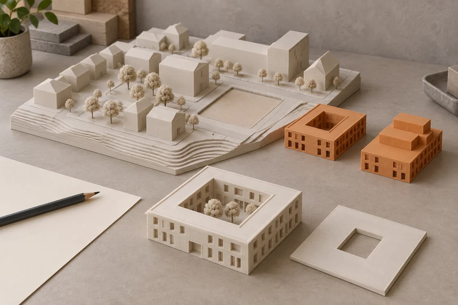
A useful architectural scale model starts with the question the client needs to answer. For Toronto architects comparing building mass, a courtyard layout or a proposal's relationship to its neighbours, prepared 3D printed components can give the meeting a shared physical reference. Choose the scale, removable pieces and detail level around that conversation.
We print authorized customer models from compatible prepared files. Your studio or model preparer handles the CAD/BIM conversion, simplification and assembly plan. A good starting brief might be: “Show two building volumes in the same context, then lift off the roof to explain the courtyard.” That is a clearer production task than “Print the project.”
Give each printed component a job
Think about what the client will do with the model. Will they look across the table at the overall volume, turn it to see a setback, or remove a roof? The answer determines which geometry matters.
MASSLAB's architects describe parcel-based models in which buildings, landscape elements, roofs and floors can be exchanged. Their example shows a practical use for modularity: keeping the context while changing the proposal.1 You can adopt that organising idea without reproducing their designs or assuming the same production results.
Use this planning table before exporting anything.
| Meeting question | Keep legible | Simplify or leave out | Useful component plan |
|---|---|---|---|
| Which massing option sits better on the site? | Building outline, height changes, setbacks and relevant neighbours | Interior systems and repeated façade detail | One context base with separate proposal inserts |
| How does the courtyard connect to the rooms around it? | Courtyard, openings and the floor relationship under discussion | Furniture and concealed services | A larger building study with a removable roof |
| What changes across a sloping site? | Ground levels, access relationships and building positions | Unrelated terrain beyond the chosen extent | A bounded terrain base, tiled if necessary |
| Does this particular edge or opening read correctly? | The feature being discussed and enough surrounding geometry to orient the viewer | Most of the full site | A separate larger-scale detail model |
For a hypothetical two-option meeting, use the same site extent and neighbouring masses for both alternatives. Keep the underside identification consistent with your drawings. Avoid changing the colour scheme, base and scale at the same time as the proposal: make it easy to see what changed.
Check both the footprint and the smallest useful feature
At 1:N scale, divide each real dimension by N. Convert to the same units first. A 120 m site is 120,000 mm, so it becomes 600 mm at 1:200 or 240 mm at 1:500.
The following are our calculated hypothetical examples, not measurements from printed parts:
| Full-size feature | At 1:200 | At 1:500 | Planning consequence |
|---|---|---|---|
| 120 m site extent | 600 mm | 240 mm | Check the assembled footprint, printable volume and carrying case; tiles may be needed. |
| 3 m floor height | 15 mm | 6 mm | Decide whether floor relationships remain clear from a seated viewing position. |
| 100 mm partition | 0.5 mm | 0.2 mm | Inspect the slice; consider deliberate thickening, omission or a larger detail study. |
| 50 mm railing member | 0.25 mm | 0.1 mm | Exact reduction may lose the feature; use a simpler visual cue if appropriate. |
If your source geometry is 1:1 and the units already match, scaling to 1:200 means 0.5%; 1:500 means 0.2%. Do not apply those percentages to a file already reduced to model scale. After import, measure one known length and confirm the final overall dimensions.
Print a paper outline of the assembled model footprint. Put it on the meeting table and check the room needed for spare inserts and removed roofs. A scale that fits the printable volume may still make the important opening too small to discuss.
Use a simple detail budget: retain the features that answer the question, simplify the supporting context, and omit irrelevant geometry. Record deliberate exaggeration. If terrain is stretched vertically to make a slope more visible, its proportions change; Prusa's terrain tutorial explicitly flags this consequence.2 Keep the terrain source, extent and any vertical scaling with the model record.
Prepare a separate model-making export
Keep the project model intact and prepare a separate export for the physical study. In a Formlabs interview, Renzo Piano Building Workshop's model makers describe removing unnecessary BIM detail, adapting thicknesses and creating closed volumes. They also combine printing with handmade, CNC and laser-cut components.3 That specialist workflow is useful preparation evidence; its resin-printing results do not establish the finish of our filament prints.
For your export, review walls, slabs, openings and the underside of the base. SketchUp's official guidance requires solid groups, outward-facing surfaces and actual volume: a hollow object still needs thickness in its walls.4 Check the geometry rather than relying on the rendered appearance.
Export parts with consistent units and origins. SketchUp documents export-unit controls and exporting selected assembly geometry separately.5 Whichever CAD tool you use, verify a known dimension after importing the result into your slicer. Keep an assembly reference so that separately exported pieces retain their intended relationship.
A model that looks right on screen can still lose fine features in slicing. Prusa distinguishes nozzle-related detail in the plane of the print bed from layer-height effects on vertical and sloping surfaces.6 Reducing layer height alone is therefore not a dependable way to recover a missing mullion or railing. Inspect the actual toolpaths for the selected profile.
Split the model where it needs to move
Give a seam a purpose. A parcel boundary can separate alternatives; a floor line can reveal an interior; a base tile can make the model easier to transport. A detachable roof needs a place to grip it and somewhere to rest during the discussion.
Print orientation and support contact also belong in this decision. Prusa's modelling guidance explains that splitting can allow more useful orientations and reduce supports, while surfaces printed over supports have a different finish.7 Inspect the support contact on façades you expect people to examine. A seam may be preferable to a prominent supported face, but check it in a representative sample.
Choose alignment features deliberately. PrusaSlicer's cut tool documents plugs, dowels and snap connectors.8 Those tools create geometry; they do not prove that your assembled model will fit. Allow for a trial piece and avoid assuming that every joint needs a tight snap fit. For something removed repeatedly, the useful test is whether it seats, lifts out and seats again without damaging the visible model.
Order a small sample when a roof edge, joint or fine façade controls the result. Include the actual mating geometry and orientation. Dry-fit it, handle it as you would in the meeting, and inspect it under normal light. Prusa's guidance notes that fit depends on several variables and requires iteration rather than one universal clearance.7 Revise and reslice before committing the rest of the components.
Leave room for assembly and presentation
The print order is one step in the studio's model-making schedule. Plan time for inspection, dry fitting, your assembly and any finishing you arrange separately. Keep permanent bonds separate from parts intended to move.
Our proposed final check is a short rehearsal:
- Assemble the context and verify the proposal against the intended revision.
- Swap each alternative and remove and replace the roof without forcing it.
- Check that the key feature is visible across the actual meeting table.
- Mark the scale, revision and deliberately simplified or exaggerated features on an accompanying card.
- Pack removable pieces separately and include an assembly reference.
Consider transport and storage conditions when selecting from currently available materials, including possible heat exposure.7 Do not leave the material decision until you have already prepared the final slice.
Paper or card remains worth considering for a simple volume study. A hybrid model can combine a separately made base with printed inserts. When the commission depends on very fine detail or a highly finished display object, discuss it with a specialist model maker or another suitable process provider. Use the physical model alongside the project's drawings and analysis; it does not validate survey accuracy or planning compliance.
Send prepared files for a Toronto print order
Our core upload path accepts compatible pre-sliced .3mf and .gcode files. An unsliced .3mf may use the opt-in auto-slice path when available. A Revit project, Rhino file, SketchUp project, raw STL, drawing or survey is not a direct checkout file, and CAD/BIM conversion is not included.
Use our STL-to-print-ready guide to understand the geometry-to-toolpath step, then slice and export the plate using a compatible profile. For prepared components across several plates, the multi-plate order guide explains the export and order structure. Our print-cost checklist can help you review avoidable support and print time after the model's purpose is settled.
Confirm permission to reproduce the project and included third-party context. Check the client's disclosure expectations before submitting; accepted customer uploads have no automatic deletion deadline. Review our terms, then upload the prepared file, choose from stocked materials and approve the CAD quote. Free scheduled Toronto pickup and Canada Post shipping are subject to the available ordering options. Allow for your own sample, revisions and assembly when planning the meeting date.
For repeated base tiles or interchangeable model pieces, adapt the sample-to-batch acceptance record to preserve the checked interface and preparation revision.
For a pull profile or decorative trim decision, the interior-design mockup guide compares a room miniature with a loose actual-size sample and a separate finish reference.
For small event decorations, the corporate-event prop guide extends the seam plan through finishing, assembly photographs and packing for the next setup.
For a product explanation rather than a site proposal, the demonstration-model guide connects the chosen scale and removable view to the visitor question.
Questions from architectural model planning
Should I choose 1:200 or 1:500?
Calculate the footprint and the smallest feature you need to explain at both scales. A hypothetical 120 m extent becomes 600 mm or 240 mm respectively. Use the smaller overall study for context if it remains useful, and consider a separate larger detail model for an opening or interior relationship.
Why do thin walls disappear in the sliced preview?
Their reduced geometry may be too small for the selected profile to produce useful toolpaths.7 Check the units and scale first, then inspect the feature in preview. Deliberately simplify or thicken it, or move the discussion to a larger-scale study. A visible toolpath still needs a handling test.
Can roofs and buildings be removable?
Yes, if your prepared design separates those components and includes a workable assembly plan. Check alignment, access for lifting and repeated removal with a sample. Uploading several parts does not by itself establish their fit.
Are sanding, painting and assembly included?
No. Plan those tasks within your studio or arrange them separately. We print the prepared customer model; we do not provide an architectural model-making or CAD conversion package.
Sources checked
Prusa: How architects at MASSLAB utilize 3D printing. Named-practitioner account of modular parcels and removable building elements; manufacturer-published case, not an independent performance test. verified: 2026-10-05.
Return to text: 1
Prusa: How to print maps, terrains and landscapes. Vertical scaling changes terrain proportions; historical tutorial, not verification of a particular site's data. verified: 2026-10-05.
Return to text: 1
Formlabs: Architectural models at Renzo Piano Building Workshop. Model-maker interview on BIM simplification, volume and hybrid fabrication; mainly a resin-printing workflow. The scale examples above are independently calculated. verified: 2026-10-05.
Return to text: 1
SketchUp: 3D printing a model. Official guidance on solid groups, surface orientation and wall volume. verified: 2026-10-05.
Return to text: 1
SketchUp: Importing and exporting STL files. Export units and selected-part export; STL is an intermediate in our workflow. verified: 2026-10-05.
Return to text: 1
Prusa: Nozzles with different diameters. Distinguishes nozzle and layer-height effects on detail; does not establish our available hardware or accuracy. verified: 2026-10-05.
Return to text: 1
Prusa: Modelling with 3D printing in mind. Guidance on orientation, supports, fine features, material conditions and iterative fit. Machine-specific dimensions are not adopted as service specifications. verified: 2026-10-05.
PrusaSlicer: Cut tool. Documents cuts and connector geometry; fit must be checked for the submitted design. verified: 2026-10-05.
Return to text: 1
Have a sliced file ready?
Upload it for an instant quote in CAD.