3D printed handle-layout templates for cabinet installers
Updated · 9 min read
A printed cabinet handle template starts with an approved layout. Record exact fixing centres, named edges and handedness, then check one sample on scrap.
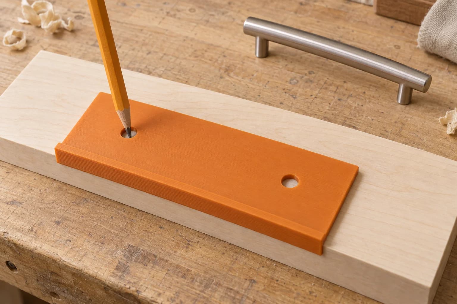
A 3D printed cabinet handle template can transfer an approved pair of fixing centres onto repeated doors or drawer fronts. Its useful job is straightforward: seat against a named front edge, mark the centres, remove the template, then drill using your established installation procedure. Before it touches finished fronts, check one print on representative scrap with the actual pull.
The important work happens before marking: separate the pull's hole spacing from its position on the front, decide which surfaces the template follows, and prove the left- and right-hand setups. A template can repeat a wrong layout just as readily as a right one.
Start with fixing centres, not the handle's overall length
Write down the exact hardware identifier and its centre-to-centre fixing dimension. Overall length describes the visible pull; it does not necessarily tell you where the screws go. For example, IKEA lists BAGGANÄS handle 003.384.07 as 143 mm long with 128 mm hole spacing.1
Keep the units explicit. Five inches equals 127 mm, so “about five-inch centres” is not a specification for a 128 mm pull. Kreg's listed drill-guide settings distinguish five inches and 128 mm.2 Confirm the actual hardware before choosing a file named only by its nominal size.
Then record placement separately. Kreg's manual makes this distinction in its commercial jig setup: the pull dimension sets the two guides, an edge guide sets the distance from the workpiece edge, and a window aligns a marked centreline.3 A printed marking template needs the same decisions, even when its positions are fixed rather than adjustable.
Consider a hypothetical 600 mm-wide slab drawer front with a horizontal pull on 128 mm centres, centred across its width. The two fixing centres would be:
(600 − 128) ÷ 2 = 236 mmfrom the left edge;(600 + 128) ÷ 2 = 364 mmfrom that same edge.
Their distance below the top remains a separate approved dimension. This example shows the arithmetic; it does not recommend a handle height. Check the chosen appearance, grip position and neighbouring fronts with the real pull before freezing the layout.
Name the edge and face that establish the marks
“Offset from the edge” leaves too much open. Specify the top, bottom, left or right outer edge of the front, plus the finished face on which the template sits. If the design uses a corner stop, identify both edges. If it uses a notch, identify the centreline that must meet that notch.
A slab front and a stepped Shaker front need different seating checks. Look for a lip landing on a rounded edge, a plate bridging a recessed panel, or a stop contacting a rail instead of the intended outer boundary. True Position Tools documents spacers that support its drilling guide over recessed Shaker panels.4 That is a useful reminder to resolve the contact geometry; it does not validate a similar-looking printed design.
Include any protective tape or pad in the trial setup. Confirm that the contact surfaces are clean and that the tool seats without rocking or marking the finish. Changing the contact arrangement after checking the sample means checking the seating again.
Check a left/right pair as two setups
Do not assume that turning a template over creates the opposite-door layout. A registration lip may work on only one face. Rotating the tool may exchange top and bottom references, or move the marks away from the meeting edge of paired doors.
True Position's instructions explicitly flip its tool to the reverse side for opposite doors.4 That reversibility belongs to its design. For your printed template, either verify both working orientations or prepare a clearly distinguished left/right pair.
On scrap, name each face and reference edge in the same way you will on the cabinet. Make both sets of marks, then measure each independently. Repeat this check for upper and lower doors if their layouts use different vertical references. A matching pair of prints is not evidence that both have been used correctly.
Keep a setup record beside the template
We suggest the following record for a shop drawing, job sheet or template storage bag. It is an original practical checklist, not a published installation standard. Fill it out before ordering the sample; complete the final column during the scrap trial.
| Record | Write down before printing | Check with the received sample |
|---|---|---|
| Hardware | Pull identifier, revision and exact fixing centres, with units | Actual pull matches the recorded spacing |
| Front | Front type, thickness and relevant edge/profile | Representative scrap reproduces the contact geometry |
| Reference | Named outer edge or edges, working face and any centreline | Stop and notch contact the intended references |
| Placement | Separate edge-to-centre offsets and centring calculation | Each mark agrees with independent layout measurements |
| Handedness | Left/right orientation; upper/lower differences | Both setups place the marks correctly |
| Marking method | Pencil or other selected marking tool | Opening permits a clear centre mark without ambiguous movement |
| Surface contact | Tape, pads or other planned protection | Same arrangement seats consistently and leaves the surface acceptable |
| Version | Model and sliced-file revision | Checked sample and saved files carry the same identification |
This record also makes a reprint easier to assess. “The orange jig from the last kitchen” is a weaker reference than a file revision tied to a particular pull and layout.
Trial the marks on scrap before drilling finished fronts
Choose scrap that represents the edge, profile and thickness relevant to the template. A flat board will not reveal a seating problem caused by a stepped front.
First inspect the print: check the contact face, stop, flatness and marking openings. Seat it, make the marks, remove it, then reseat and repeat on another area. Compare the marks against measurements taken independently of the template. Check both fixing spacing and edge offsets; matching spacing alone cannot establish correct placement.
Use the marking tool you intend to use on site. Confirm that its tip reaches the surface and produces a centre you can identify. Prusa's workshop article documents a printed tool that carries a pencil along a board edge to mark parallel lines.5 It supports the edge-marking concept, but supplies no cabinet-specific accuracy or service-life result.
Next, remove the template and drill the trial marks using your normal equipment and procedure. Fit the actual handle to the scrap and review the result before moving to finished fronts. Keep the backer used during drilling separate in your thinking: Kreg recommends scrap behind the workpiece to prevent exit chip-out.3 That backer does not replace the earlier layout trial.
Reject a sample that rocks, gives ambiguous marks or disagrees with the approved dimensions. Correct the relevant geometry and reslice; avoid scaling the entire model to fix one offset because that also changes the hole spacing and other features. Recheck after a revision or a changed pull/front combination. The trial evaluates that particular setup, not a universal tolerance guarantee.
Choose between a marking template and drilling tooling
Check the tools already available before arranging a custom print. Measuring individual fronts or making a scrap template may suit a small, varied job. IKEA's FIXA is a retail marking option with a strip that registers against a door or drawer-front edge.6 A printed template becomes a candidate when an authorized model provides the particular stop, contact shape or approved fixed layout you need.
Direct drilling is a separate tool choice. Kreg documents hardened-steel drill guides in its commercial cabinet jig.2 In UltiMaker's ERIKS case study, engineer Jesse Ippel describes revising a printed drilling jig's fit and adding a press-fit metal tube to protect its guide opening.7 These are documented drilling-tool approaches with additional design and component considerations.
An ordinary printed marking opening is not equivalent to that tooling. For the workflow here, mark and remove the template. If you need direct drilling, select and validate suitable drilling equipment for the application. Our print order does not include engineered tool qualification, drill bushings or their assembly.
Prepare the file for a Toronto print order
Start with a model you own or have permission to reproduce. Keep its source URL, revision, licence and any required attribution with the setup record. Creative Commons licences differ: attribution may be required, NonCommercial terms restrict commercial use, and ShareAlike terms place conditions on adaptations.8 A downloadable file alone does not settle permission for paid reproduction; resolve uncertainty before uploading.
We print authorized customer models supplied as compatible pre-sliced .3mf or .gcode files. If your starting point is an STL, follow our STL-to-print-ready guide, then the plate slicing and export instructions. An unsliced .3mf has an opt-in auto-slice path, subject to availability. CAD work and model modification are separate preparation tasks.
Order one sample before the working quantity. Choose from the stocked materials shown in the quote flow, and account for your storage and use environment, including a hot vehicle, sunlight or cleaners. We do not specify one material or print recipe for every template.
Once the file is ready, upload it for a CAD quote. Review the available ordering options for free scheduled Toronto pickup or Canada Post shipping, and keep the accepted sample's files for any repeat order. Our terms describe the service boundaries.
When a template will be reused across properties, adapt the maintenance file-library record to retain the hardware identifier, front profile and accepted template revision.
Other bench offsets and finish-sample supports call for different shapes; our millwork guide and painting-stand article covers seating checks and contact marks.
Before committing to a custom pull shape, compare interior-design form mockups; approving visual bulk is a separate decision from marking its fixing centres.
Questions installers ask
Can one template cover different pull sizes?
Only if its design provides the exact marking positions you need and each selected setup has been checked. Overall pull length is not enough to choose a hole pair. Record the fixing centres for every hardware variant.
Can the same print work on both doors?
Possibly. Check the registration lip, working face and reference edges in both orientations. Where reversal changes the seating or mark locations, use a verified left/right pair rather than improvising on finished fronts.
Does door overlay change a front-edge offset?
Blum defines overlay and inset by the door's relationship to the cabinet frame.9 Our practical inference is to establish which object the approved layout references. If it references the front's own outer edge, do not automatically add or subtract a hinge-overlay value. A layout referenced to the cabinet opening needs its own explicit measurements.
Can I drill through the printed marking holes?
That is outside this marking workflow. Remove the template after transferring the centres. Direct drilling needs suitable tooling and its own checks; the metal-guide examples above do not establish that a plain plastic opening is a drill guide.
Sources checked
IKEA Canada, BAGGANÄS 003.384.07 measurements — one identified pull's overall length and hole spacing. Verified: 2026-10-05.
Return to text: 1
Kreg, Cabinet Hardware Jig specifications — listed spacing settings and hardened-steel guides; no claim about printed-template performance. Verified: 2026-10-05.
Kreg, KHI-PULL owner's manual, English setup/use pages — separate pull spacing, edge offset and centreline alignment; scrap backer advice. Verified: 2026-10-05.
True Position Tools, Cabinet Hardware Jig instructions, pages 4, 7 and 9 — scrap checks, reverse-side door setup and recessed-panel spacers for the documented tool. Verified: 2026-10-05.
Prusa, 3D printed workshop equipment: tools and jigs — firsthand pencil-through-hole edge-marking example. Verified: 2026-10-05.
Return to text: 1
IKEA Canada, FIXA drill template — retail edge-referenced marking alternative; local stock not checked. Verified: 2026-10-05.
Return to text: 1
UltiMaker, custom jigs at ERIKS — named engineer's fit iterations and metal guide insert in an industrial example. Verified: 2026-10-05.
Return to text: 1
Creative Commons, licence explanations — attribution, NonCommercial and ShareAlike conditions; general information, not clearance of a particular model. Verified: 2026-10-05.
Return to text: 1
Blum, CLIP top BLUMOTION technical information, page 7 — overlay, dual and inset definitions; no handle-placement rule. Verified: 2026-10-05.
Return to text: 1
Have a sliced file ready?
Upload it for an instant quote in CAD.